
The quality of the edges and the cleanliness of the fold depend entirely on the balance between Spindle Speed (RPM) and Feed Rate. Here is the approved operational matrix for 2026:
| Technical Parameter | 3mm Panels (Interior) | 4mm Panels (Exterior) | 6mm Panels (Mega Projects) |
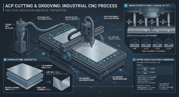
| Spindle Speed (RPM) | 18,000 – 20,000 | 15,000 – 18,000 | 12,000 – 15,000 |
| Feed Rate | 15 – 20 m/min | 12 – 15 m/min | 8 – 12 m/min |
| Tool Type | Carbide (Single Flute) | Carbide (Up-cut Spiral) | Carbide (Double Flute) |
| V-Groove Angle | 90° | 90° – 135° | 135° |
The Engineering Math of Cutting Speed
To avoid melting the low-density polyethylene (LDPE) core and prevent chip buildup that causes Delamination, you must calculate the cutting speed ($V_c$) accurately. This ensures that heat remains within safe architectural limits:
$$V_c = \frac{\pi \cdot D \cdot n}{1000}$$
Where:
- Vc: Cutting Speed (meters/minute).
- D: Tool Diameter (mm).
- n: Spindle Speed (RPM).
Expert Insight: If the edges appear “burnt” or show melted plastic, your RPM is likely too high relative to your Feed Rate, causing friction instead of a clean mechanical cut.
Step-by-Step Setup Guide
Step 1: Calibration and Stability
Perfect Flatness of the machine bed is the foundational pillar. A deviation of even 1mm in the table will result in a groove that is either too shallow (impossible to fold) or too deep (breaking the outer aluminum skin).
- Always utilize Vacuum Table systems for total board stability.
- Ensure the table is cleared of all previous debris and chips.
Step 2: Path Engineering
Do not treat all toolpaths with the same technical weight:
- V-Grooving: The most critical stage. You must leave 0.3mm to 0.5mm of the core material above the bottom aluminum layer to ensure a flexible fold without cracking.
- Straight Cutting: Use specialized aluminum bits that prevent core adhesion.
- ATC System: Relying on an Automatic Tool Changer ensures there is no depth conflict between the grooving tool and the cutting tool.
Step 3: Execution and PVDF Protection
During operation, metal chips pose a high risk to the PVDF coating.
- Use a high-powered dust collection system.
- Use a misting system only when absolutely necessary; otherwise, rely on strong air blasts to cool the bit and disperse chips, protecting your material investment.
The Strategic Pivot – Why Risk Your Inventory?
Ruining a single sheet due to incorrect settings is more than a financial loss; it creates a “bottleneck” that delays the entire project timeline. In 2026, smart factories do not rely on “guesswork” on the shop floor. They rely on Nesting Algorithms and pre-set parameters that guarantee Zero-Error production.
Instead of fixing rough edges manually after the cut (Rework), start with software that adjusts paths based on specific material properties (such as Aludecor or Unibond) to ensure the highest ROI.
Based on this technical guide, are you currently noticing “chatter” or roughness on the cut edges after grooving, or is the issue primarily centered around the aluminum skin snapping during the manual folding process?