
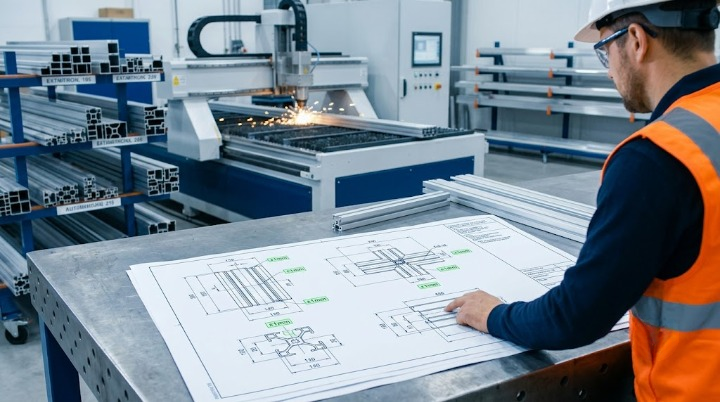
The gap between design intent and fabrication reality costs money. Vague shop drawings lead to clarification delays, rework cycles, and fabrication surprises that blow schedules. DOME FDH converts CAD into millimeter-accurate shop drawings—production-ready, clash-verified, and fabrication-proof—so your shop floor moves forward without guessing.
The Cost of Ambiguity: Why Vague Shop Drawings Stop Fabrication
Your architect’s CAD model shows the facade. Your fabricator sees it as a sketch. Somewhere between the two, details go missing.
Common shop drawing problems:Common shop drawing problems:
Unclear dimensions: Is this 2mm or 20mm? Shop floor stops to call back for clarification.
Missing section details: Where exactly does aluminum meet concrete? No callout = no certainty.
Unspecified tolerances: ±1mm or ±10mm? Wrong assumption = scrap parts + rework.
Fabrication assumptions: Shop assumes one solution; architect meant another. Discovery happens too late.
No clash callouts: This aluminum section works in the 3D model, but on paper no one sees the structural column conflict until tooling is programmed.
Each ambiguity triggers a cycle: clarification request → design revision → reissue → re-fabrication. In a typical project, three rounds of rework add 3–5 weeks to the schedule and 15–20% to material costs.Each ambiguity triggers a cycle: clarification request → design revision → reissue → re-fabrication. In a typical project, three rounds of rework add 3–5 weeks to the schedule and 15–20% to material costs.
Why Millimeter Precision Matters: More Than “Looking Good”
Precision shop drawings aren’t about perfectionism. They’re about certainty.
When your fabrication team knows exactly what to build — down to the millimeter — three things happen:
Schedule locks: No “wait and see” moments. Your team programs CNC tools once, runs production once, delivers on time.
Scrap drops: Fabricators build right the first time. Wrong dimensions disappear. Material cost baseline holds.
Installation goes smooth: On-site crews see a pile of parts that fit, that match each other, that slot together. Zero field surprises. No schedule compression due to assembly chaos.
How DOME FDH Creates Fabrication-Ready Shop Drawings
We convert CAD to production reality through a structured process:
Step 1: Dimensional Audit
We extract every dimension from CAD and cross-check against fabricator constraints (aluminum section sizes, tooling reach, standard material widths). If a dimension doesn’t fit real-world tooling, we flag it upfront, with options: slight redesign, or custom-order (and cost impact stated clearly).
Step 2: Fabrication Sequencing
We organize the facade into logical shop-build chunks. Each chunk has a numbered shop drawing with call-outs for: aluminum sections (with exact extrusion profiles and lengths), bolts/rivets (type and count), gaskets and seals (materials, dimensions), and assembly order. The sequence follows fabrication logic: frame first, then infill, then finish.
Step 3: Clash Detection on Paper
Before sending drawings to the shop, we verify clashes: does this aluminum mullion hit the concrete backup? Does this connection detail leave room for the gasket? Does the tolerance stack for bolted assembly result in jamming? We catch conflicts now, not mid-fabrication.
Step 4: Tolerance Specification
Every dimension gets a tolerance callout: ±1mm for critical fits, ±5mm for non-critical lengths, ±0.5mm for section alignment. Tolerances are tighter than shop standard where necessary, looser where appropriate—so fabricators know exactly which dimensions matter and which don’t.
Step 5: CNC-Ready Output
Our shop drawings export directly to CNC programming (DXF/DWG with layer organization, or native CAM files if your shop uses them). Dimensions are unambiguous, coordinates are absolute, and cut lists are machine-readable. Your CNC operator loads the file and starts cutting—no re-entry of data, no transcription errors.
Real Example: How Precision Saved 4 Weeks + $80K in Rework
Saudi mall renovation, 2000 m² aluminum curtain wall.
Architect’s CAD showed facade geometry. Structural consultant added mullion positions. MEP noted HVAC duct runs behind the wall. Facade contractor assumed standard tolerances.
Halfway through fabrication: HVAC duct clashes with main aluminum frame. The duct route wasn’t called out on shop drawings. Contractor had built frames assuming the original layout. Frame teardown, rework, and re-fabrication: 4 weeks lost.
DOME’s approach: We extracted all constraints upfront—structural, MEP, facade. Our shop drawings explicitly called out the HVAC duct run with “clearance required: 600mm” callouts. Mullion spacing adjusted to avoid clashes, with cost delta shown: +3% material, but zero rework.
Outcome: Fabrication on schedule. Installation finished 4 weeks early. Rework cost: $0. Client happy.
Frequently Asked Questions
Q: How long does it take to create shop drawings from CAD?
A: Typical facade (2,000–5,000 m²) takes 3–5 working days. Complexity (curved geometry, many interfaces) adds time. We provide a timeline upfront based on scope.
Q: What if we need revisions after shop drawings are signed?
A: We include 2 rounds of revisions in our fee. Changes after that are charged hourly. Most revisions are minor (tolerance tweaks, paint spec changes) — major redesigns trigger a new drawing cycle.
Q: Can we use your shop drawings with any fabricator?
A: Yes. Our drawings are independent of fabricator. They specify what needs to be built, not how. Any qualified shop can execute from our drawings.
Q: Do you provide shop drawing support during fabrication?
A: Yes. We’re available for clarifications and on-site support if issues arise. Typical response: within 4 hours.
Q: What file formats do you provide?
A: PDF (signed, marked-up), DWG (layered, AutoCAD-native), and DXF (CNC-ready). We can also export native CAM formats (IGES, STEP) if your shop uses parametric modeling.